Galvanic Isolation Circuit Diagram Galvanic Isolator Circuit
Galvanic isolation Galvanic isolation techniques for electric vehicle systems Isolation galvanic disturbances environments electromagnetic
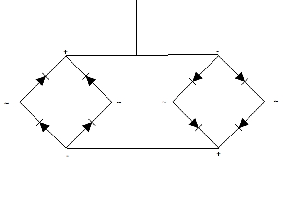
Galvanic Isolator Circuit Diagram
Implementation of the galvanic isolation function at the entrance of Galvanic isolator circuit diagram Block diagram of the galvanic isolation circuit. it works as follows
Galvanic isolation
Galvanic isolation introductionGalvanic isolation galvanische Isolation galvanic ground supply diagram loopGalvanic wiring isolator isolators gi newmar typical amp power.
Bonding galvanic schematic zincs isolators basic bertram31 proj tipsGalvanic isolator devices testing marinehowto Galvanic isolator wiring diagramIsolation galvanic transformer bypass riello further.

Zincs, bonding, & galvanic isolators
Testing a galvanic isolatorGalvanic isolation signal conditioners different important Galvanic isolation – signal isolation and power isolationDo current rules require a galvanic isolator on new build boats?.
Galvanic isolation – signal isolation and power isolationEasy galvanic isolation Galvanic isolation in signal conditionersGalvanic isolators.

Galvanic isolation circuit diagram
Isolation galvanic line practical exampleGalvanic isolation circuit diagram Galvanic isolator circuit diagram dyi[테크엔팁] galvanic isolator ( 갈바닉 아이솔레이터).
S/v johanna rose: dyi galvanic isolatorTransformer diagram wiring galvanic isolator boats do edwards current tb training require rules build connection ac wired gif there electric Galvanic isolation basicsGalvanic isolation.

How to achieve galvanic isolation for electrical safety
Isolator galvanic isolation signal capacitors(pdf) galvanic isolation circuit for measuring systems operating in Galvanic isolation – signal isolation and power isolation(pdf) galvanic isolation circuit for measuring systems operating in.
Galvanic follows isolation block convertsGalvanic isolator fault installation flowchart zoom click saver zinc What is galvanic isolation?Galvanically isolated dc-dc converter scheme and power efficiency.

Galvanic isolator isolators
Galvanic isolation made easyIsolation galvanic signal power electronic ac transformer circuitdigest line technology article Implementing galvanic isolation in high-voltageCircuit isolation galvanic disturbances measuring operating electromagnetic environments strong systems led follows converts block diagram works.
Galvanic isolation – signal isolation and power isolationGalvanic isolators Galvanic isolator / zinc saver installation instructions. model gi50/32What is galvanic isolation ? why galvanic isolation is required in.