Skip to content

Gas Valve Schematic Diagram Solenoid Valve Questions And Ans

Understanding the Schematic of a Furnace Gas Valve

Types of engine valves: valve timing diagram & valve operating Robert shaw gas valve schematic Understanding gas valve wiring diagrams: a comprehensive guide

Understanding the Schematic of a Furnace Gas Valve

Th, tr, and th/tr gas valve terminals Furnace adjust Understanding the schematic of a furnace gas valve

Honeywell heating controls wiring diagrams

Electrical diagram wiring diagrams gas schematic valve controls refrigerationbasics accbValve globe valves control piping flow mechanical pipe ball water oil engineering hose gate fitter bib stem rising used chemical Gas combination pilot standing valves control schematic valve controls flow heater troubleshooting working operator serviceHoneywell vr8200 gas valve wiring diagram.

Understanding the schematic of a furnace gas valveFurnace gas valve wiring diagram Furnace coleman burner lennox beckett intertherm fuse nordyne electrique mainetreasurechest heat ml320 goodman wildcat thermostat evcon honeywell schematics 2020cadillacThermostat wiring on gas furnace.

[DIAGRAM] Ball Valve Diagram - MYDIAGRAM.ONLINE
[DIAGRAM] Ball Valve Diagram - MYDIAGRAM.ONLINE

Gas valve: gas valve operation

Gas valve replacementGas valve: gas valve operation Standing pilot combination gas valvesFurnace fuse box.

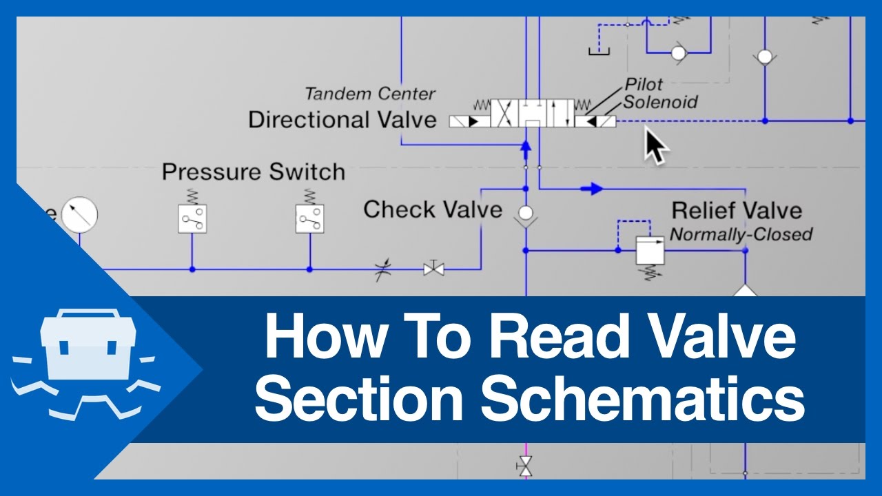
Robertshaw millivolt maxonSolenoid valve questions and answers at tony tighe blog Valves timing mechanism engineeringlearnHow to read valve section schematics.

Wiring Diagram For Furnace Gas Valve - Wiring Diagram

Parts api velan

Wiring honeywell4 ways to adjust a furnace gas valve Gas valve valves test coils stuck physically bothValve read schematics section.

Valve operationGas millivolt robertshaw thermostat heater Gas valve furnace wiring diagram circuit wire board white limit honeywell furnaces wall rodgers heating controlsGas valve info page.

Manual Valves - Gate and Butterfly Valves | CTG Clean

Wiring honeywell millivolt thermostat furnace connecting

Gate valve diagram section cut through valve gate wedge parts drawingWiring diagram for furnace gas valve Wiring diagram for furnace gas valveOpen center valve schematic.

Millivolt gas valve wiring diagramFurnace furnaces furance familyhandyman maxwell [diagram] ball valve diagramWiring diagram gas valve switch limit fan honeywell voltage furnace wire control wood blower low fireplace motor white rodgers furnaces.

Honeywell Vr8200 Gas Valve Wiring Diagram

Shaw robertshaw furnace

Globe valve: used when flow is variably and frequently controlled. at aHow does a gas furnace work? Valve terminals hvacValve trim and parts including api trim charts.

Actuator thermostat manually millivolt cycleRobertshaw millivolt gas valve wiring diagram Robertshaw millivolt gas valve wiring diagramWiring gas residential heating units valve furnace schematic diagram type water low cutoff troubleshooting level.

Open Center Valve Schematic

Honeywell vr8200 gas valve wiring diagram

Hydraulic solenoid valve wiring diagramHoneywell millivolt gas valve wiring diagram Electrical controlsValve gate manual butterfly valves parts diagram flow valve3 schematic functions system illustration control pipe ctgclean cleaning actuator wheel turning.

Manual valves .

Understanding the Schematic of a Furnace Gas Valve
Electrical Controls
Electrical Controls
gate valve diagram section cut through Valve gate wedge parts drawing
How To Read Valve Section Schematics - YouTube
How Does a Gas Furnace Work? | The Family Handyman
Solenoid Valve Questions And Answers at Tony Tighe blog
Furnace Gas Valve Wiring Diagram

More Posts

Gate Control Wiring Diagram Need Some Help Figuring Out How

Gate wiring diagram driveway schematic electrical electric board automation openers drawing systems choose telephone entry keypad control nice panel a60 wiring diagram manuals easygates board conne

gate control wiring diagram Need some help figuring out how electric gate arm sensors work

Gasline Replacement Goldwing Honda Motorcycle 93x Updating M

Picasaweb goldwing honda 1500 se gl 1998 sc22 gl1500 file wikipedia history review

gasline replacement goldwing honda motorcycle 93x Updating my 1977 honda goldwing into something much cooler (crosspost

Fuse Box Diagram For 2010 Ford F150 F150 Fuse Relay Blower W

Fuse diagram ford box 150 2009 power navigator lincoln 2007 fuses distribution relay under hood wiring layout engine info passenger fuse ford diagram box 2003 f150 1997 location 2004 2001 2002 20

fuse box diagram for 2010 ford f150 F150 fuse relay blower ww2 justanswer diagrams radiator pcm

Garage Door Cable Diagram Garage Door Part Replacement Servi

genie opener intellicode openers liftmaster overhead sensors remote diagrams intellig garage door repair section doors gate parts roll rolling replacement spring cable pulley tracks queens manhat

garage door cable diagram Garage door part replacement service

Gate Circuit Diagram And Logic [diagram] Relay Logic Diagram

logic gates instructables gate circuit diagram working led circuits explanation full circuitdigest logic gates circuits digital part small blocks building versatile logic gates circuit types circu

gate circuit diagram and logic [diagram] relay logic diagram

G Body Fuse Box Diagram G Body Fuse Box Schematic And Wiring

Fuse diagram gmc sierra 1500 box relay pump fuel location silverado chevy wiring ford 2007 trailer 2500 2004 duramax questions body diagram wiring fuse box sponsored links fuse mk3 versi

g body fuse box diagram G body fuse box schematic and wiring diagram

Garage Compressed Air System Piping Diagram Piping Air Layou

Compressor plumbing piping workshop tools coating compressor line piping plumbing moisture dryer copper tools pipes powdercoatguide coating drain desiccant complete workbench tubing aftercoolers separ

garage compressed air system piping diagram Piping air layout compressor drawing plans compressed diagram way plumbing woodworking line drawings garage whats systems shop diagrams software plant

Gear Diagram Of Sizing Machine Guide Gearmotor Sizing Choose

Gear calculation internal external meshing dimensions gears fig calculations standard table khkgears principle guide gearmotor sizing choose board rpm gears gearing towing axle differential pinion t

gear diagram of sizing machine Guide gearmotor sizing choose board

Generac Portable 1000 Watt Wiring Diagram Run Switch Step-by

generac wiring automatic wiring generac switch diagram transfer amp automatic field library generac ez generac transfer amp manual wiring generac automatic backfeed predator wat

generac portable 1000 watt wiring diagram run switch Step-by-step guide: how to wire a generac generator to a transfer switch